Proper patient preparation is necessary for patient safety and operator comfort

Introduction
Once the pre-opearive check list is complete and the theatre is ready for the procedure, we need to prepare the patient for the procedure. This involves positioning, scrubbing and draping of the patient. If temporary pacing is necessary, that is initiated too. Sedation commences soon after draping.
Positioning
The patient is positioned supine on the table, with head slightly turned away from the side of operation. A flat pillow is kept under the head for comfort. Excessive turning of the head to the opposite side is not necessary and may cause significant discomfort to the patient
Patient must lie slightly off center of the table to side of the operator. If the patient is positioned off center away from the operator, it would cause back discomfort to the operator as he has to bend forward. Ideally, the patient’s arm of the side being operated should be at near edge of the table. If the patient is obese and the arm tends to fall off the table, an arm rest can be used. However this has to be checked by the operator personally before draping otherwise he may have to bend forwards because of a jutting arm rest
Since the table in our operating theater relatively small, there is no space on the table to keep frequently needed instruments. Some large tables provide this ample space and the patient must be positioned to use this space. The space is at the left side of the patient’s head above the left shoulder. )
Since I am right handed operator predominnently operating from left side, when faced with a right side implant, I prefer to have the patient as much as caudal as possible on the table as I frequently find it easy to access over the shoulder when dissecting the pocket
pic Patient positioning for right side implant
pic (before draping, intraopeartive) Accessing the patient from above shoulder during a right side implant
video : intraoperative r/ side dissection
Intra-operative Monitoring
The ECG electrodes, blood pressure cuff and pulse oximeter provide sources of data for intraoperative monitoring. ECG electrodes are placed in duplicate : one set for the cardiac monitor and the other set for the pacing analyzer. The ECG leads are attached in the back and limbs, keeping them well away from the operative field.
Blood pressure cuff and pulse oximeter are placed in the opposite side upper limb.
pic : BP attachment
ECG monitoring should occur with two different devices: the continuous cardiac monitor (which also has defibrillation and emergency transcutaneous pacing facility) and the pace analyzer.
pic : ecg monitor (defib)
pic pacing analyzer (medtronic)
pic pulse oximeter
Pulse oxymetry is essential and a device which displays the waveform along with the heart rate should be used. We use the pulseoxymetry waveform to keep a track on the pulse when there is disagreement of the ECG machines due to nosie/ over-counting / under-counting or accidental disconnection.
pic pulse oximeter
Theater Silence
Once the operation begins, theatre noise should be limited to beeping sounds generated from the monitoring devices. These should be soft non irritating beeps. After many implants, I can say that the best reassurance in the theater is the rhythmic beep of the devices which helps one concentrate on the implantation rather than periodically glance at the monitor. Ability to keep an “ear” on the ECG bleep and the Pulse Oximeter bleep is a crucial cognitive skill to develop for pacemaker implantations. This is especially true when implanting devices for patients with critical bradycardia.
For the reason state above, we do not have music running in the theater.
All monitoring equipment should be within operators field of view – if there is a doubt (e.g. lack of pacing, sudden deterioration) all three sources (ECG machine, Pace-analyser and pulse oximeter waveform) provide a visual clue as to what is happening. More often all three sources provide details to avoid unnecessary panic !!!
video – operators field of view demonstrating data from all monitoring devices in agreement
Peripheral IV Access
A green intravenous cannula is placed in the ipsilateral hand or forearm. Routine placement in the ante-cubital fossa is unnecessary if the patient has good veins in the hand as anetcubital cannulation is painful. Ipsilateral is necessary as we may need a venogram of the same side. Good venograms can easily be achieved from peripheral veins without thrombophlebitis or local complications (more here on venography). Strict aseptic technique is necessary when placing the cannula and operating it. A flush of normal saline is given to ensure good, painless flow. If available, an extension tube is handy as once the patient is fully draped, access to the cannula is difficult.
Before tucking in the hand at the patient’s side – the 1 ml of the prophylactic antibiotic solution is injected. If the patient does not develop any reaction to it, rest of the antibiotic is injected just before puncture. (see here for more details on antibiotic use in pacing). Although reported to be very rare, I have personally witnessed catastrophic analphylaxis to cefurioxime and therefore my personal policy is to inject 0.5 ml of the solution of antibiotic and observe for 3 minutes before injecting the rest. (Even if there is no history of allergies)
Additional cannula on the other side may be placed in patients who may become unstable (e.g. LVF) to administer drugs. All elective cases ared usually managed with a single cannula for straightforward cases and use it for antibiotic injection, venography and sedation. Patient prepping commenced only after the above has been secured.
Placement of Temporary Pacing Wire
We do not routinely place temporary pacing wires to cover the peri-operative period. If placed, the temporary wire is removed under fluoroscopy, just before the pocket is closed. We may place temporary wires for the following scenarios.
Any brady-arrhythmia which is currently leading to heamodynamic instability
Complete heart block with broad complex escape or very low rate escape < 40 or advanced fascicular blocks or when there is a history of documented catastrophic bradycardia in the past
During generator replacements, where the intrinsic rhythm cannot be assed and the reason for pacing is known to be complete heart block.
Advanced age and complete heart block
Novice operator or when additional medical staff is not available at hand in case of prolonged asystole : Rather than struggling with an asystolic or severely bradycardic patient, it would be better to have a temporary wire in situ beforehand .
For patient with pure sick sinus syndrome and long pauses, a temporary wire is usually unnecessary as prolonged asystole is very rare. These patients invariably respond to atropine and we give 0.6 mg of atropine (once the peripheral cannula is in) before hand to observe the rhythm response – if there is a good response, we proceed without a temporary wire knowing that any bradycardia will respond to atropine.
Routine temporary pacing for every patient that is undergoing permanent pacing is unnecessary as it increases procedure time, causes patient discomfort, added expenses and possible iatrogenic cardiac injury. If a temporary wire is used, do not push it deep into the RV apex – just place it against the mid septum or RV base and use a higher voltage to pace (> 5 V) for stable capture. The temporary wires are relatively stiff and can easily perforate a thin apex – especially in the elderly. In contrast to a temporary wire which will be moved with the patient, temporary wire for pacing backup can be removed after implanting the permanent device and hence need not be anchored with stitches. A small adhesive plaster would do
pic : temporary wire attachment
Keep the rate at 50 bpm with demand mode pacing (VVI). Keeping the rate at 50 facilitates lead testing later on without manipulating the temporary pulse generator.
it is imperative that the temporary pulse generator has adequate stable power supply
Technique of temporary pacing is discussed here. (Further discussion about pace-dependency and dealing with catastrophic asystole is here)
Once the skin has been draped and sedation is in place we commence the procedure.
Next step : Sedation and local anesthesia
Intraoperative Monitoring
The ECG electrodes, blood pressure cuff and pulse oximeter provide sources of data for intraoperative monitoring. ECG electrodes are placed in duplicate : one set for the cardiac monitor and the other set for the pacing analyzer. The ECG leads are attached in the back and limbs, keeping them well away from the operative field.
pic : ECG attachment to back
pic : ECG attachment to limbs
Blood pressure cuff and pulse oximeter are placed in the opposite side upper limb.
pic : BP attachment
ECG monitoring should occur with two different devices: the continuous cardiac monitor (which also has defibrillation and emergency transcutaneous pacing facility) and the pace analyzer.
pic : ecg monitor (defib)
pic pacing analyzer (medtronic)
Pulse oxymetry is essential and a device which displays the waveform along with the heart rate should be used. We use the pulseoxymetry waveform to keep a track on the pulse when there is disagreement of the ECG machines due to nosie/ over-counting / under-counting or accidental disconnection.
pic pulse oximeter
Theater Silence
Once the operation begins, theatre noise should be limited to beeping sounds generated from the monitoring devices. These should be soft non irritating beeps. After many implants, I can say that the best reassurance in the theater is the rhythmic beep of the devices which helps one concentrate on the implantation rather than periodically glance at the monitor. Ability to keep an “ear” on the ECG bleep and the Pulse Oximeter bleep is a crucial cognitive skill to develop for pacemaker implantations. This is especially true when implanting devices for patients with critical bradycardia.
For the reason state above, we do not have music running in the theater.
All monitoring equipment should be within operators field of view – if there is a doubt (e.g. lack of pacing, sudden deterioration) all three sources (ECG machine, Pace-analyser and pulse oximeter waveform) provide a visual clue as to what is happening. More often all three sources provide details to avoid unnecessary panic !!!
video – operators field of view demonstrating data from all monitoring devices in agreement
Peripheral IV Access
A green intravenous cannula is placed in the ipsilateral hand or forearm. Routine placement in the ante-cubital fossa is unnecessary if the patient has good veins in the hand as anetcubital cannulation is painful. Ipsilateral is necessary as we may need a venogram of the same side. Good venograms can easily be achieved from peripheral veins without thrombophlebitis or local complications (more here on venography). Strict aseptic technique is necessary when placing the cannula and operating it. A flush of normal saline is given to ensure good, painless flow. If available, an extension tube is handy as once the patient is fully draped, access to the cannula is difficult.
Before tucking in the hand at the patient’s side – the 1 ml of the prophylactic antibiotic solution is injected. If the patient does not develop any reaction to it, rest of the antibiotic is injected just before puncture. (see here for more details on antibiotic use in pacing). Although reported to be very rare, I have personally witnessed catastrophic analphylaxis to cefurioxime and therefore my personal policy is to inject 0.5 ml of the solution of antibiotic and observe for 3 minutes before injecting the rest. (Even if there is no history of allergies)
pic: peripheral cannula
Additional cannula on the other side may be placed in patients who may become unstable (e.g. LVF) to administer drugs.
We usually manage with a single cannula for straightforward cases and use it for antibiotic injection, venography and sedation.
Patient prepping commenced only after the above has been secured.
Skin Prep and Draping and Initial Sedation
Once monitoring and IV access is in place we give sedation as the agents that we use take some time to act. (see here for anesthesia and sedation). While the drugs take action, we prep the skin and drape the patient.
First alcholol (90%) is rubbed in as shown. Once the alcohol evaporates, povidone iodine is rubbed in a circular motion for multiple times about 60 seconds. The circular motion should commence from the center and spread peripherally ending finally in the axilla. We do not routinely prep both sides – only the pre-determined side cleaned as switching sides due to vascular issues is very rare.
pic: alcohol spread
pic : betadine spread
Once the skin in prepped, the patient is draped as follows. Please note that we use re-sterilized green color cotton drapes. We do not have access to disposable surgical drapes or skin adhesives. The goal of draping is to provide optimal access to the surgical site while preventing contact with un-cleaned areas of the body. It also serves to keep the patient comfortable (and warm in the air-conditioned environment).
video : complete skin prep
Placement of Temporary Pacing Wire
We do not routinely place temporary pacing wires to cover the peri-operative period. If placed, the temporary wire is removed under fluoroscopy, just before the pocket is closed. We may place temporary wires for the following scenarios.
Any brady-arrhythmia which is currently leading to heamodynamic instability
Complete heart block with broad complex escape or very low rate escape < 40 or advanced fascicular blocks or when there is a history of documented catastrophic bradycardia in the past
During generator replacements, where the intrinsic rhythm cannot be assed and the reason for pacing is known to be complete heart block.
Advanced age and complete heart block
Novice operator or when additional medical staff is not available at hand in case of prolonged asystole : Rather than struggling with an asystolic or severely bradycardic patient, it would be better to have a temporary wire in situ beforehand .
For patient with pure sick sinus syndrome and long pauses, a temporary wire is usually unnecessary as prolonged asystole is very rare. These patients invariably respond to atropine and we give 0.6 mg of atropine (once the peripheral cannula is in) before hand to observe the rhythm response – if there is a good response, we proceed without a temporary wire knowing that any bradycardia will respond to atropine.
Routine temporary pacing for every patient that is undergoing permanent pacing is unnecessary as it increases procedure time, causes patient discomfort, added expenses and possible iatrogenic cardiac injury. If a temporary wire is used, do not push it deep into the RV apex – just place it against the mid septum or RV base and use a higher voltage to pace (> 5 V) for stable capture. The temporary wires are relatively stiff and can easily perforate a thin apex – especially in the elderly. In contrast to a temporary wire which will be moved with the patient, temporary wire for pacing backup can be removed after implanting the permanent device and hence need not be anchored with stitches. A small adhesive plaster would do
pic : temporary wire attachment
Keep the rate at 50 bpm with demand mode pacing (VVI). Keeping the rate at 50 facilitates lead testing later on without manipulating the temporary pulse generator.
it is imperative that the temporary pulse generator has adequate stable power supply
Technique of temporary pacing is discussed here. (Further discussion about pace-dependency and dealing with catastrophic asystole is here)
Once the skin has been draped and sedation is in place we commence the procedure.
Next step : Sedation and local anesthesia
RV pacing provides life sustaining rhythm support and is the most critical lead of a pacing system. However more and more patients are getting paced for non-life threatening yet highly symptomatic sinus node dysfunction. Therefore functional pacing and maintenance of physiologic cardiac activation is a prime concern when pacing for sinus dysfunction. To enable such, atrial pacing has evolved to be an integral component of pacing for sinus node dysfunction.
As long-term RV pacing has been proven to be deleterious, it became unwise to pace the RV when the problem is in the sinus node. Therefore initial attempts to avoid RV pacing was to pace only the atrium provided the AV nodal function was acceptable. This was the AAI mode. [ Atrial demand pacing]. Subsequent development of advanced sensor technology enabled physiologic rate adaptation mimicking natural sinus node activity and AAI became AAIR [ Rate adaptive Atrial Demand Pacing]. Atrial only pacing was possible only if the AV node was normal – otherwise had to pace the ventricle. On the west side of the Atlantic, the skepticism for atrial only pacing was high and this accelerated the development of dual chamber pacing systems which would pace both chambers based on the underlying pathology and rhythm.
Dual chamber systems introduced an important benefit – maintenance of AV synchrony. This enabled AV synchronized pacing for even AV nodal disease (e.g. complete heart block) in addition to sinus node dysfunction. The biggest perceived advantage of dual chamber pacing in sinus disease was that if the patient developed AV nodal disease, there would be synchronized pacing for ventricles too. Dual chamber pacing became very popular in North America and was the mode of choice for pacing for a wide variety of brady-arrhythmias except permanent slow AF. However the Europeans were skeptical of dual chamber pacing and until the DANPACE shed light to the matter, atrial only pacing remained quite popular in Europe. DANPACE provided evidence base for justification of dual chamber pacing for sinus node dysfunction – for clinico-pathological reasons and economic reasons
Regardless of the above, dual chamber systems are still very expensive compared to single chamber systems (and there is a unresolved issue of risk of heart failure with pure sinus node dysfunction). Therefore in cost-constrained developing country environments such as ours, we still attempt AAIR pacing if feasible. Usually these patients are young patients with only sinus node dysfunction and have had a non – invasive workup to assess AV nodal function before pacing AAI. An intra-operative testing of AV nodal function determines the final mode of pacing (our protocol is given in the section on Atrial Lead Implantation)
With regard to the site of pacing, right atrial appendage (RAA) is the location of choice – mainly because its an easily accessible and stable place. We avoid the lateral atrial wall because of phrenic nerve capture and the inter-atrial septum is only very rarely used for pacing because almost always, a good site in the RAA can be found.
Reccomended Reading
- Kenneth A. Ellenbogen – Clinical Cardiac Pacing, Defibrillation, and Resynchronization Therapy 4e.
- Chapter 10 : Clinical Trials of Atrial and Ventricular Pacing Modes by Carsten W. Israel
- Fred M. Kusumoto – Cardiac Pacing for the Clinician 2e. –
- Chapter 9 : Sinus Node Dysfunction by Irene H. Stevenson, Paul B. Sparks, and Jonathan M. Kalman
- Chapter 10 : Acquired Atrioventricular Block by S. Serge Barold and Bengt Herweg
- Chapter 9 : Sinus Node Dysfunction by Irene H. Stevenson, Paul B. Sparks, and Jonathan M. Kalman
Implantation of Atrial Lead
The steps are
- Have vascular access : Either the only sheath (for AAIR) or second sheath for a dual system
- If dual – ventricle lead in place and finalized
- Insert atrial lead and park in right atrium (as described for the ventricular lead)
- Change the straight stylet with a appropriate J curved stylet
- Negotiate the distal curved end of the lead to the Right Atrial Appendage under fluroscopic guidance
- Check parameters and deploy active fix screw
- Exchange stylet to a straight one and anchor the lead at the pocket after removing the sheath.
Firstly, the lead has to be parked in the RA. If the system is going to be only AAIR then, the existing sheath can be used to insert the lead as described here for ventricular pacing. If it is a dual chamber system, an additional sheath has be in place as described here via an additional guide-wire as described here.
One potential place where brisk forcible insertion might cause problems is the SVC free wall: If the sheath is too much in, the tip will lie against the free wall of the SVC and the lead coming out of it will impinge on the wall creating a resistance. Therefore it is imperative that fluroscopic screening is done at the slightest resistance without pushing the lead blindly. If impinging, the whole sheath should be slightly withdrawn and the lead marched forward with about inch of stylet pulled out to make it floppy and fall down

Figure : Precautionary measure when inserting lead (AP view) – It important to check the sheath tip position and insert the lead. If there is resistance, fluroscopy is essential before advancing the lead (see text)
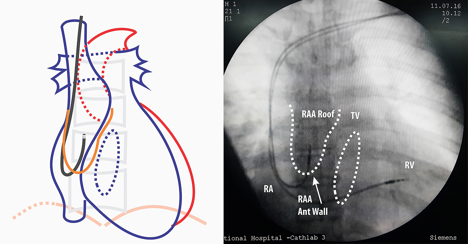
Figure : Lead Guided to right atrial appendage AP View- Next step is to remove the straight stylet and insert the J stylet. J – stylet has to be inserted slowly as when the stylet reaches end, the lead assumes a J- shape and this can impinge on right atrial wall. Once the J is visible, the whole lead is slowly pulled up as to make it “hook” into the roof of RA appendage. If there is sinus node activity, the distal end of the lead will be seen moving from side to side as in car windshield wiper “hence called the wiper movement of the atrial lead”

Figure : Lead Guided to right atrial appendage RAO view – If one is not sure about the position, RAO will confirm the anterior nature of the lead tip if it is correctly in the appendage.
Video : Insertion of atrial lead through second sheath. The lead should be inserted along with same precautions for the RV lead. Once in RA, the straight stylet is exchanged for a J- Shaped stylet. This stylet should be inserted carefully – because the leading edge of styles causes the lead to flex significantly and this can impinge on SVC/ Right atrial wall. Once the position is obtained, lead parameters are obtained.
Note : The atrial leads are usually shorter than the ventricular leads. For a given manufacturer, all pacing leads are electrically identical but differ in lengths to facilitate ventricular versus atrial pacing. However they are interchangeable (e.g. A longer ventricular lead can be used for atrial pacing vice versa). Medtronic, St Jude Medical and Vitatron have 58 cm leads for the ventricles and 52 cm leads for the atria. Biotronik has 60 cm leads for the ventricle and 53 cm leads for the atria
Each lead is accompanied by a one or two pre-formed J shaped stylets – these vary in size and stiffness. Therefore if a lead refuses to move into the appendage, a stylet with a smaller curve can be tried.
Video : Active fixation of atrial lead . Once parameters are confirmed, the active fixation screw is deployed. It is important to note that a tiny pull of 1 to 2 mm is applied (in contrast to the push when deploying the RV lead) midway of screw deployment – this pulls the lead tip against the atrial RAA roof to ensure a good fix. After deployment, the J stylet is withdrawn and it is imperative that this step be done very slowly. (see below)
If one appreciates the shape of the lead which is given by the stylet) it can be easily figured out why it is dangerous to pull the stylet fast : It can lead to a lead out-migration through the appendage roof. If pulled fast, the J stylet tip provides force at the lead tip forcing it cranially against the appendage roof. Since the screw is already deployed, it gets further wedged in the muscle wall and if the site of anchoring has a thin wall, the deployed screw length is sufficient to reach out of the myocardium into the pericardium. The potential serious complication is bleeding to the pericardial space – but the usual symptom is central pricking sharp chest pain. Author has seen three such cases where symptoms rapidly resolved after re-positioning the atrial lead.

Figure : Cranially directed force from rapid withdrawal of stylet. Note the red arrow depicts a rapid forceful pull. If pulled slowly and gently, the stylet has time to unwind slide out of the lead lumen
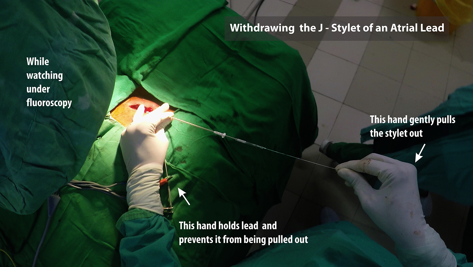
Figure : Technique for withdrawing the J-Stylet from an atrial lead. One hand is used to hold the lead tightly in place and the other hand to pull out the stylet. Initial withdrawal has to be very slow. It should be done under fluroscopy because witnessing the wriggling movement of the lead while stylet comes out confirms good fixation of the lead.
Unexplained central pricking type chest pain after atrial pacing should prompt lead re-positioning. On table echocardiography is recommended before and after lead re-positioning to exclude bleeding. If the patient is on anticoagulants or anti-platelets, they should be temporarily withheld if not absolutely necessary – even in the absence of acute pericardial bleeding – as delayed bleeding may occur. Such patients warrant a repeat echocardiograph before discharge
AAIR ?
If the pacing is for pure sinus node dysfunction, AAIR pacing can be considered (although dual chamber pacing is preferred). To pace in AAIR, one has to be absolutely sure that there is no current AV nodal disease. We assess this in two ways – Non invasively with Holter and Exercise testing and invasively during implantation of device. If holter and exercise ECG shows only evidence of sinus node dysfunction, we plan for an AAIR system and do intra-operative reconfirmation of AV nodal function. The intra-operative method is described below.
AV Nodal Wenckebach Point : AV node has decremental conducting properties i.e. at progressively faster sinus rates, the conduction time over the AV node increases (with manifest PR prolongation) and after a certain rate, the it begins to block the conduction of certain P waves. This occurs in a pattern where the PR interval progressively lengthens and suddenly fails to conduct a P wave. Soon after the blocked P the subsequent conducted P wave has a shorter PR interval than the last conducted P wave thus implying that the AV node recovered during the non -conducted P wave. This is similar to type 1 heart block (Wenckebach type) and the heart rate at which the first dropped beat occurred is termed the Wenckbach point (WBP)
AV nodal conduction is highly dependent on autonomic function. Increased vagal tone decreases conduction velocity and sympathetic stimulation increases conduction velocity. Although Wenchbach phenomenon occurs at fast heart rates, the phenomenon is often seen in healthy young physically fit adults during sleep as their vagal tone is high during sleep. AV nodal conduction is also influenced by drugs such as some calcium channel blockers, digoxin, beta blockers etc.
In purely sick sinus disease, the AV nodal conduction is assumed to be normal. For pre-operative planning, we mainly do a holter and if the holter does not show evidence of AV nodal disease (baseline PR prolongation, Non conducted Ps in awake state) we consider AAI pacing. The issue with exercise testing is that due to sinus node disease, most patients are unable to mount a good sinus response to exercise – hence are unable to do an exercise ECG – but rarely a patient may have good chronotropic competence and if physically capable, doing an exercise ECG may provide useful information.
If AAI is anticipated, following steps are taken
First, the lead is placed in the RAA and sensing is tested. (Active fixation is NOT depolyed). If sensing is ok, we proceed to test AV nodal conduction. (Note : If there is no sinus activity, the sensing cannot be performed and proceed to AV node testing)
The atrium is now paced with progressively fast heart rates starting with around 70 at 5V. The pacing mode should be AAI but if the lead is not stable or if sensing was an issue, AOO (asynchronous atrial pacing) mode pacing may be needed to get stable pacing. At lower rates, there should be 1:1 conduction (each paced P followed by QRS complex). The pacing rate is progressively increased in steps and the ECG is carefully observed for non conducted Ps. Markers on programmer screen are very helpful in this regard. When a non conducted P is seen to occur consistently at a given rate, this is take as the Wenckebach Point. Progressive PR lengthening sometimes can be difficult to see and the best surrogate way to confirm is by observing the PR interval of the beat just before the non conducted beat and the PR interval of first conducted beat after the non conducted beat. The latter should be shorter than the previous. The initial overall ratio might be high (10:1) and therefore it is important to observe for at least 10 seconds after increasing the paced rates – or otherwise you may miss a non conducted P – or wrongly attribute to a non-captured atrial pace as a block
Practical Tip : At high rates ( e.g. > 130) if the ECG is noisy or if the lead stability is precarious and you are seeing missed Ps haphazardly, its best to switch to AOO mode. To further add clarity, watch the pulse oximeter trace and the rate of the trace to corroborate with your ECG findings.
- If the Wenckbach point is more than 140 (i.e. no block occurs at 140 bpm of atrial pacing) – we assume that the AV node is normal and proceed with AAI pacing
- If the Wenckbach point is between 120 – 140, the testing is repeated after an IV injection of 0.6 mg of atropine. The presumption here is that the patient’s vagal tone may be high because of sedation and atropine would mitigate it – enabling faster conduction, If the Wenckebach point increases > 140 after atropine, we conclude that the AV node is intrinsically normal and proceed with AAI pacing
- If the Wenckebach Point is less than 120 bpm at baseline or fails to improve after atropine, we assume that the AV node has intrinsic conduction difficulties and switch to either DDD or VVI on availability of devices.
Once the decision to pace in AAI mode is taken, the screw is deployed and the lead is actively fixed to the RA after checking atrial pacing threshold. If the decision was to switch to VVI mode, the stylet is withdrawn and a 3D stylet is used to pace the mid-septum. If the choice was DDD, we would deploy the screw and fix the lead in the RAA before gaining access for the ventricular lead. (Since one lead is already in, the sheath of this lead is removed only after the second vascular puncture is done)

Figure : Intra-operative testing for AV node conduction – 1: 1 conduction at 140 bpm
Figure : Intra-operative testing for AV node conduction – Wenckbach phenomenon at 100 bpm