Insertion and Placement of Guide-wires for Cardiac Pacing
Placing the First Guide Wire
The guide wire forms the basis of the access to the vein and enables application of seldinger technique for passing sheaths to the vein.
The guide-wire forms the basis of the access to the vein and enables application of seldinger technique for passing sheaths to the vein. It has a coiled structure with a highly flexible curved (floppy) tip, a relatively sturdy body and a floppy but straight end. The tip facilitates entry and navigation into the vessel, the body gives firmness to transport sheaths over it and the tail facilitates loading of sheath at that end. An introducer nozzle facilitate entry of the guide wire to the puncture needle by making the floppy end temporarily straight
The guide wire should always be sent inside from its curved floppy tip. The straight tail end should never be advanced in front as it may tear through a vessel or right atrial wall with catastrophic consequences. The implanter should personally check that the wire is indeed in the correct orientation as the introducer nozzle may mask wire tip.
Video : Insertion of the guide wire. The guide-wire should go in smoothly without any resistance. Once it is in the desired position (IVC), the protruding end needs to be clipped on to the drape to prevent accidental pull out.
The guide wire should go in smoothly and if resistance is felt, advancement should be stopped and wire path must be checked by fluoroscopy. In any case the final resting point for the curved end of the wire should be at the level of the proximal inferior vena cava (on the right side of the spine, just below the right atrial silhouette). Having the wire in the IVC confirms that the wire is indeed the venous system of the heart (not the arterial side). This position also prevents accidental wire prolapse into the right ventricle that can trigger ventricular arrhythmia or cause unstable degrees of heart blocks by traumatizing the conduction system. Usually 2/3 of the wire should go in without any resistance and 1/3 remain outside.
If there is late resistance, fluoroscopic examination of the shoulder and ipsilateral neck should be done as the wire could have passed up the internal jugular vein. If there is early resistance, the needle may have come out of the vein into the pre-pectoral tissues – necessitating fluroscopic evaluation and advancement.
Once the wire has been successful placed, the next step is creating the pocket. The straight end of the wire should be clipped to a stable part of the draping using an artery forceps, to keep it away from interfering with the creation of the pocket and to prevent it from being accidentally pulled out. If the initial component of the guide-wire is seen descending on the left side of the spine and crossing it to enter the right artrium or IVC, a persistent left sided superior vena cava has to be entertained. A good venogram (using more volume than for a standard venogram) has to be done to delineate the anatomy. It is recommended that the wire be kept in and the venogram done from an arm cannula to highlight the the wire path instead of withdrawing the wire and giving contrast through the puncture needle. (if contrast is given through the puncture needle, there is always a chance of contrast extravasation by a misplaced needle.) The most important thing that the operator should ascertain is that the wire is not in the aorta as a left sided SVC is an exceedingly rare occurrence.
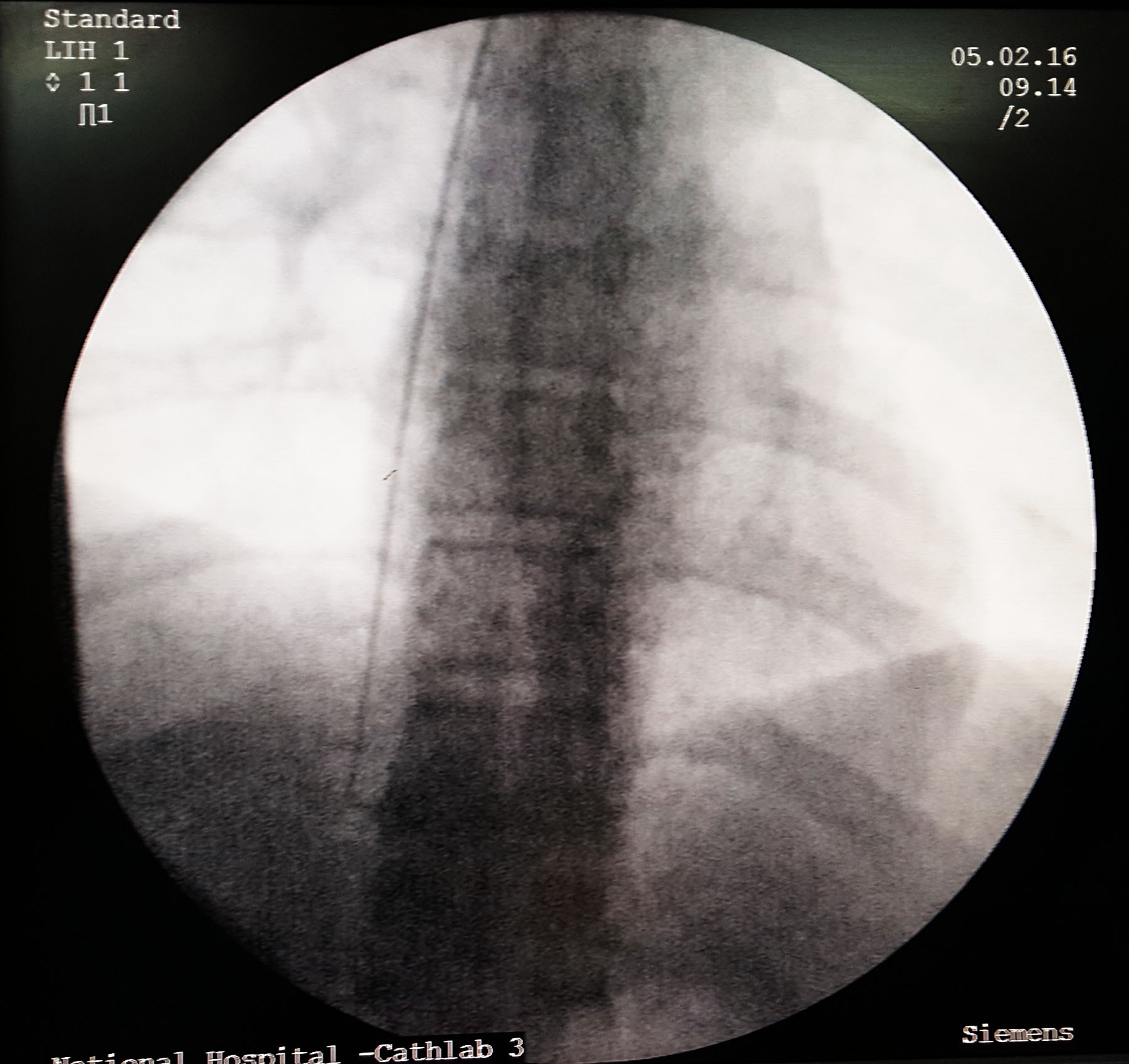
Figure : Radiographic appearance of wire in inferior vena-cava. This is the safest position to assume that the guide wire is in the correct venous path. Occasionally one may find it difficult to advance into the IVC and tend to advance it into the RV with resulting ventricular ectopics. if such occurs it also confirms the correct path – but better to withdraw the wire slightly and keep it in the RA as a floating wire can rarely trigger a VT from the RV
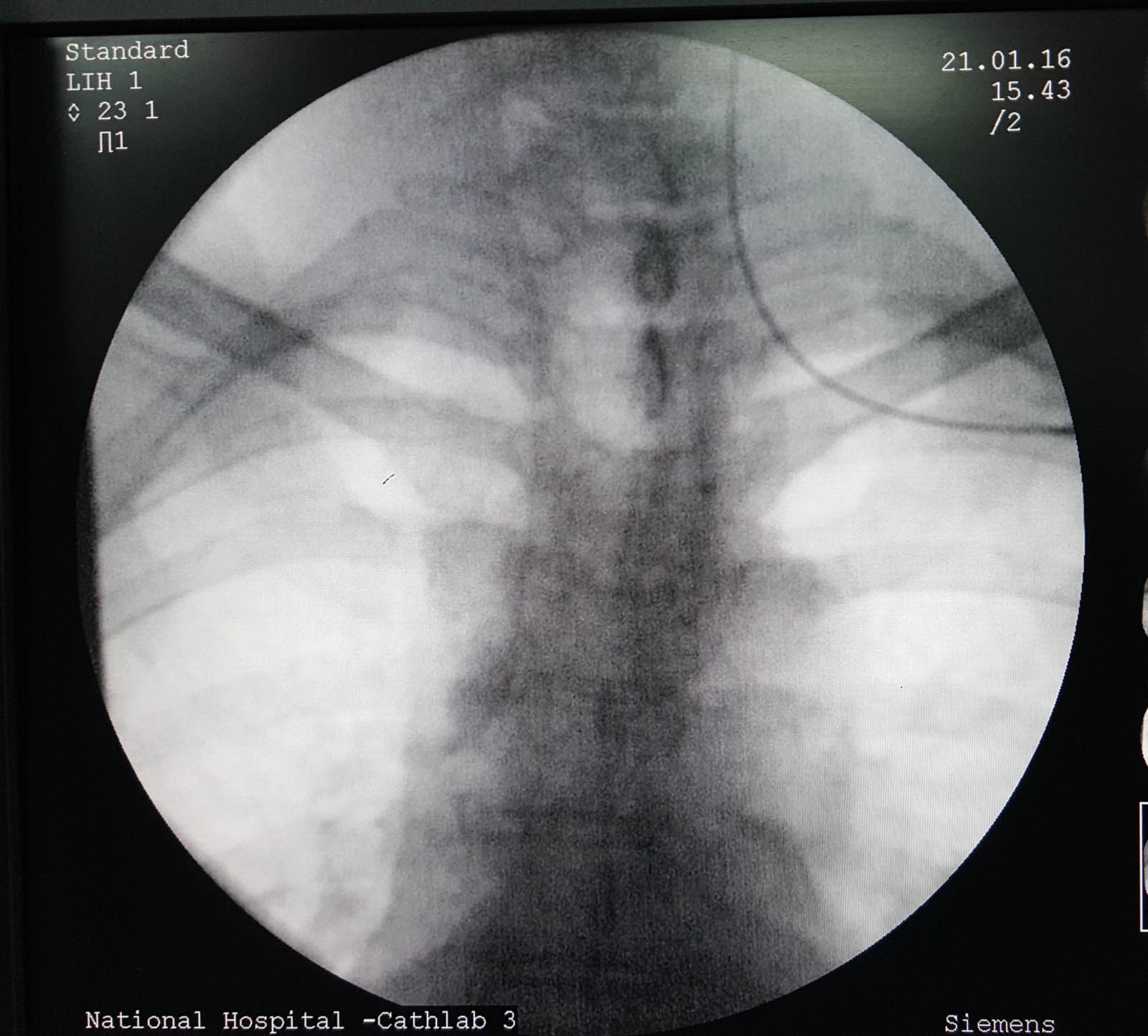
Figure : Radiographic appearance of wire inadvertently placed in the ipsilatral internal jugular vein. Usually when this happens, there is delayed resistance to the passage of guide-wire (in contrast to early resistance if a block in the axillary or subclavian vein) – Obviously the wire needs to be withdrawn and directed to the correct site.
Video : Ensuring guidewire is in indeed in the vein by making it go in to the IVC
Once the wire has been successful placed, the next step is creating the pocket. The straight end of the wire should be clipped to a stable part of the draping using an artery forceps, to keep it away from interfering with the creation of the pocket and to prevent it from being accidentally pulled out. If multiple leads are planned, the necessary wires can be placed now or through the pocket once the pocket is created. We prefer to put additional wires once the pocket has been made as having multiple wires jutting out of the skin makes creating the pocket cumbersome. Additionally making the punctures through the pocket gives the operator more flexibility in choosing appropriate spacing between the leads in the pocket floor.
If guide-wire advancement fails within the venous system, an obstruction must be excluded by venography if already not done. If venography shows a patent but tortuous vessel, an a coated guide-wire(e.g. Terumo wire) can be passed down instead of the standard guide-wire. Coated wires generally negotiate through bends and tortuosities- however this must be done by an experienced operator as although the vein may support a coated wire, it may not subsequently support advancement of the pacing lead. The implanter has to judge on the feasibility of getting in the pacing lead as well.[ A long sheath may facilitate lead passage through a tortuous vein but this has to be attempted by an experienced operator. Furthermore long sheaths are not always available for standard pacing] If there is a doubt about the venous patency, it is always better to switch to the opposite side if possible.
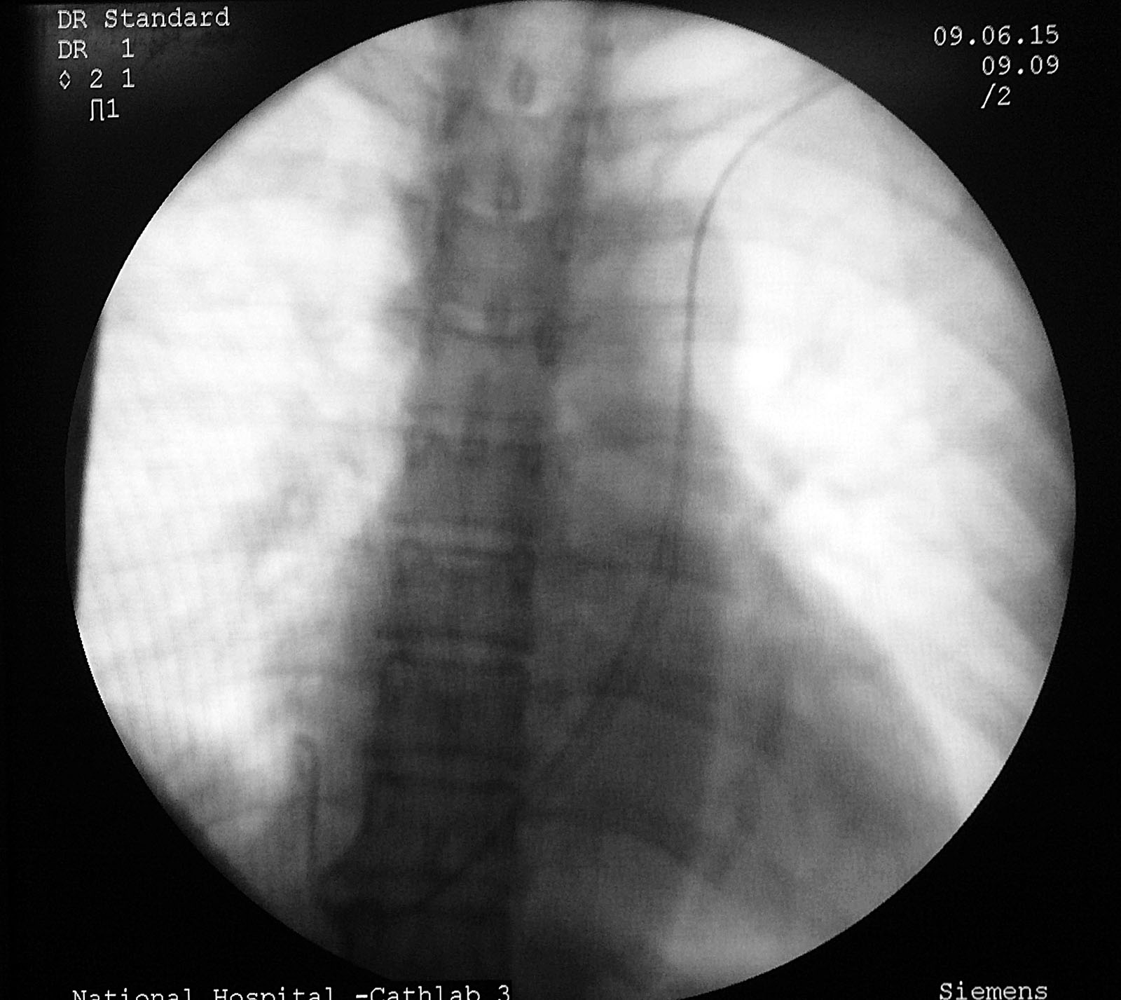
Figure : An example of wire in a possible persistent left SVC configuration. The wire is seen to descend on the left side of the spine and cross it at the lower part of the cardiac silhouette to lie in the right atrium. In the upper part, the wire “appears” to be in the aortic shadow but in the lower part it has crossed the mid-line to the right side.
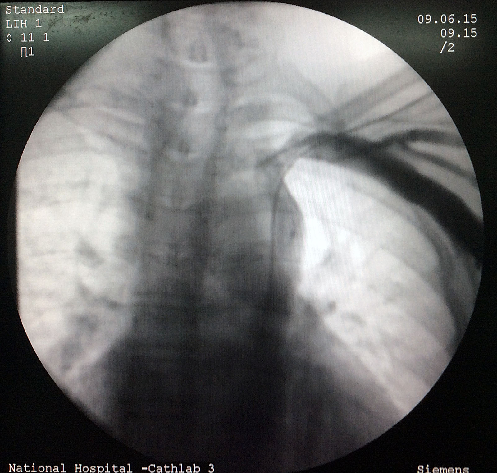
Figure : The patient in the previous image, being given a good injection of contrast to delineate the left upper limb venous drainage and thereby confirming the presence of a persistent left SVC
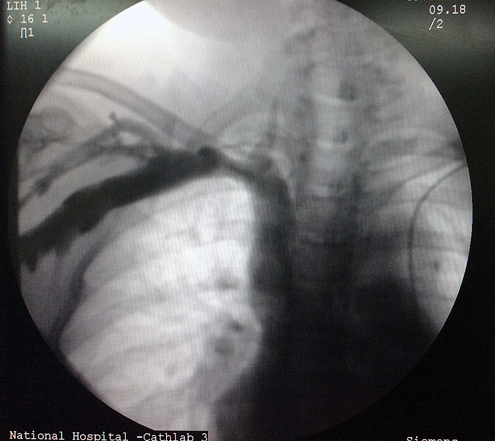
Figure : the same patient receiving contrast from the right arm to further delineate the upper extremity drainage and this study confirms the presence of a right sided SVC too. It is important to check the opposite side beforehand to know the options for pacing as sometimes the right SVC may be totally absent with right subclaivan draining to the left SVC
Venogram : Subtle indication of the presence of a L/SVC.
Guidwire in L/SVC: Guidewire tracking down on the left side of spine and curving to reach the right side behind the heart (coronary sinus). If the wire fails to show this path – there are two possibilities – L/SVC and wire indeed in the Aorta – either ascending or descending. Only a good venogram while the wire is in place will tell the difference.
Placing Additional Guide-wires
In multi lead systems (e.g. dual chamber pacemakers), more than 1 guide-wire is necessary for additional sheaths. The author’s preferred way of getting additional wires in is by doing additional punctures guided by the existing wire. Additional punctures are done through the pocket floor, few mm away from the first guide with fluoroscopic guidance . One must be careful with regard to depth, as puncturing through the pocket means shallow entry to the vein (compare to puncturing through skin). Once the second wire is in, its position is confirmed radiographically. The medial most wire is selected for the atrial lead sheath and clipped to the drapes and kept away. The sheath dilator set assembled, flushed and inserted along the free guide-wire thus establishing a sheath for the ventricular lead. The second method is to use the double wiring or piggy back method – which is described in the following link